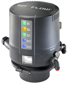
DT4 - Tank Outlet Double Seat Mixproof Valves
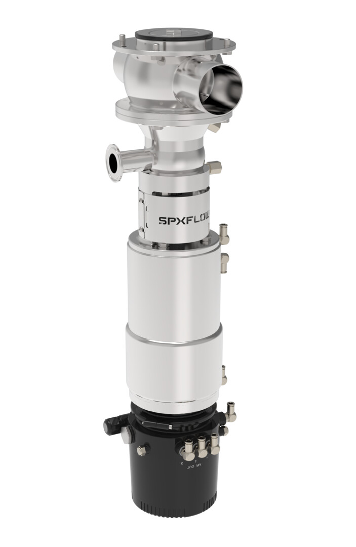
The DT4 tank outlet mix proof valve is used for the reliable separation between the tank and servicing pipeline. The DT4 tank outlet is an extension to the D4 Series mix proof family which helps fulfil today’s customer demands for production flexibility, increased productivity, rapid return on investment (ROI) and improved product quality in the food and drink, dairy, personal care and brewing process industries.
FEATURES
High value, Low life cycle costs:
- “All-In” standard features such as seat lift actuator and cross-port housing provide exceptional value
- Reduced inventory costs with same seal kit used on multiple size ranges: DN40-DN65 (1.5”-3.0”) and DN80-DN100 (4.0”)
- Low air consumption and air supply requirements
- Leak drain with clamp connection for CIP fluid collection
- Long housing ports ease manifold building
- Integrated shaft seal flush reduces need for external piping
Reliable performance:
- Design based on the proven D4SL model
- Tank side holding pressure greater than 5 bar (73 PSI)
- Long stroke for gentle product handling (ex: particulates) and low flow resistance
- Balanced design helps to prevent hydraulic blocking and enables flexible flow direction without slamming
- Heavy-duty bolted flange connection between tank/housing/insert provides secure, controlled assembly/disassembly of valve insert
- No compressed air needed for removal and servicing
- Range of control units and bus communication for automated operation
Cleanability:
- Designed to the latest global hygienic standards
- Cavity spray cleaning as standard
- Radial seal design provides minimal switching leakage
- Extensive cleaning of product contact seals
View the SPXFLOW D4 Mix Proof Valve Maintenance (Chinese) video.
How do tank outlet valves work ?
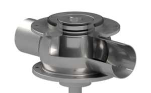
Double seat mix proof valves are used to safely process two different fluids efficiently (typically product and CIP) through the valve simultaneously. The DT4 mix proof design has two independently operating seats that separate the tank and pipeline when the valve is in the fail-safe closed position. The atmospheric vent cavity between the seats creates a path to exit through the leakage chamber should the seals fail, as well as a drain for CIP solution during seat cleaning. External CIP spray flush connections are included to provide enhanced cleaning of the leakage vent cavity as well as the lower shaft, while the valve is closed or open during production.
Product in Blue
Valve Closed |
Optional Lower Seat Clean |
Valve Open |
Optional Upper Seat Clean |
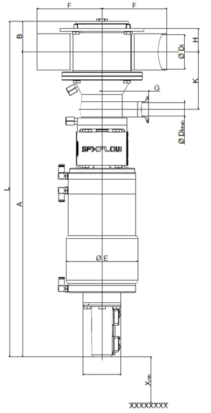
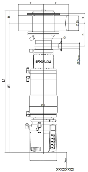
DIMENSIONS & SPECIFICATIONS
DT4 SL
Dimensions mm | A | A1 | B | øDi |
øDi Drain |
øE | F | G | H | K | L | L1 | X* |
DN | |||||||||||||
40 | 551,2 | 602,6 | 45 | 38 | 26 | 138,2 | 125 | 89,5 | 31 | 97 | 596,2 | 647,6 | 100 |
50 | 569,2 | 620,6 | 51 | 50 | 26 | 138,2 | 125 | 89,5 | 37 | 103 | 620,2 | 671,6 | 100 |
65 | 587,2 | 638,6 | 59 | 66 | 26 | 138,2 | 125 | 89,5 | 45 | 111 | 646,2 | 697,6 | 100 |
80 | 654,6 | 706 | 67,5 | 81 | 26 | 192,2 | 142,5 | 146,5 | 51,5 | 122,5 | 722,1 | 773,5 | 100 |
100 | 664,1 | 715,5 | 77 | 100 | 26 | 192,2 | 142,5 | 146,5 | 61 | 132 | 741,1 | 792,5 | 100 |
INCH | |||||||||||||
1.5 | 549,6 | 601 | 46,6 | 34,8 | 26 | 138,2 | 125 | 89,5 | 32,6 | 95,4 | 596,2 | 647,6 | 100 |
2.0 | 568 | 619,4 | 52,2 | 47,6 | 26 | 138,2 | 125 | 89,5 | 38,2 | 101,8 | 620,2 | 671,6 | 100 |
2.5 | 584,35 | 635,75 | 56,15 | 60,3 | 26 | 138,2 | 125 | 89,5 | 42,15 | 108,15 | 640,5 | 691,9 | 100 |
3.0 | 590,65 | 642,05 | 62,45 | 72,9 | 26 | 138,2 | 125 | 89,5 | 48,45 | 114,45 | 653,1 | 704,5 | 100 |
4.0 | 662,9 | 714,3 | 78,2 | 97,6 | 26 | 192,2 | 142,5 | 146,5 | 62,2 | 130,8 | 741,1 | 792,5 | 100 |
*Minimum installation and valve insert removal dimensions